Access-Aware Top-Level Routing
Top-level routing starts only after generated modules have been placed, repaired for well-domain constraints, and assembled hierarchically.
The router therefore does not work with individual transistor terminals. It sees generated child cells whose matching structures, dummy devices, local buses, diode connections, stack-node routing, and other local connections have already been completed internally.
The remaining task is to connect the exported module interfaces without destroying that local analog structure.
This requires more than ordinary point-to-point routing. A long module bus, a capacitor plate, a guard ring, and a small signal terminal are different physical routing objects and should not be accessed through one generic pin model.
Routing Plan
The flow first builds a routing plan which combines:
- placed module interfaces;
- transformed top-level terminal geometry;
- module-local connectivity information;
- effective top-level pins;
- boundary-access candidates;
- module blockage regions;
- routing-corridor and outside-whitespace hints;
- guard-ring terminals;
- remaining net classes.
This plan acts as a contract between generation, hierarchical assembly, and the routing stages.
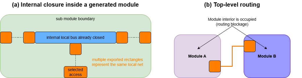
Collapsing Internal Closure
A generated module may export several physical terminal geometries that belong to the same net.
If generator metadata confirms that those geometries are already joined inside the child cell by a local bus or other safe internal route, the top-level flow does not attempt to reconnect each geometry independently.
Instead, the internally connected group is collapsed into an effective top-level endpoint.
This preserves the hierarchical responsibility boundary:
- local analog closure remains inside the generated module;
- only unresolved inter-module connectivity is exposed to the top-level router.
The approach also avoids redundant top-level wires over a net that has already been closed inside a child cell.
Net Classification
After internal closure has been collapsed, the remaining routing tasks are classified according to the connection treatment they require.
| Net class | Top-level treatment |
|---|---|
| Single-pin interface | Export as a top-level interface |
| Supply or bulk-related net | Apply supply/bulk-aware handling |
| Point-to-point signal | Route between two effective endpoints on different modules |
| Multi-terminal signal | Connect incrementally to a growing routing tree |
| Guard-ring connection | Use extended guard-ring access geometry |
The classification is therefore performed after internal closure, not directly from the original netlist.
Access-Safe Geometry
Electrical terminal geometry and routing access are related but distinct.
A terminal can be:
- a long gate, source, or drain bus;
- a small signal-access rectangle;
- a capacitor plate;
- a guard-ring edge;
- an explicitly exported boundary terminal.
The complete conductive geometry defines the electrical terminal. The top-level router should connect only through geometry that is marked or inferred as safe for top-level access.
For a long bus, the nearest bus edge may be preferable to the geometric centre.
For a capacitor plate, an existing plate edge or generator-defined access structure may be valid while an arbitrary new via/contact stack is not.
A guard ring is exposed to the router as an extended connectable edge region.
The access model therefore allows the top-level flow to choose among existing bus edges, capacitor-plate edges, exported boundary access, and extended guard-ring regions.
Boundary Access
An endpoint is used directly when its exported geometry is already safe for top-level routing.
If the terminal is not directly usable but can be conservatively extended to the module boundary, the top-level flow can generate a short boundary access segment.
This access segment:
- belongs to the top-level layout;
- does not modify the generated child cell;
- provides a safe endpoint for later inter-module routing.
Boundary access is not added unconditionally.
When two compatible routing objects can already be connected safely and directly, the flow prefers the direct connection and suppresses an unnecessary access segment.
Terminals that lie too deeply inside a generated module and cannot be safely exposed through the generic boundary-access policy are left for topology-specific access handling rather than forcing an unsafe route through the module interior.
Guard-Ring and Bulk Routing
Guard-ring routing is separated from ordinary signal routing.
A guard ring is represented as a large connectable region with several possible access edges. Treating it as one point pin would discard this geometry and could force a long or physically poor connection.
When two or more same-net guard-ring terminals must be joined, the router builds an incremental tree:
- select a short legal initial pair;
- create the first guard-ring connection;
- treat the connected geometry as the current routing tree;
- find the nearest legal connection from an unconnected guard ring to the current tree;
- attach it and update the tree;
- repeat until the required terminals are connected.
Candidate routes are evaluated using Manhattan distance together with module-blockage interaction.
When a guard ring must connect to a source-like or bulk-related terminal, the signal-side terminal first obtains a safe access location; the guard-ring route then connects to that access rather than entering the child module arbitrarily.
Point-to-Point Signal Routing
Point-to-point routing handles nets with two effective endpoints on different modules.
The process first resolves access-safe endpoint geometry.
The inter-module route is then selected from Manhattan candidates while treating unrelated module regions as routing blockages.
The main route should not cross a generated module interior. Only short escape geometry associated with the endpoint’s own module is allowed when required by its access policy.
Routing corridors and available whitespace are therefore preferred over paths that cut through unrelated child-cell regions.
Nearest Bus-Edge Access
A long bus is not reduced to its centre point.
When a compatible connected bus component is available, the router can select the nearest useful bus edge or endpoint relative to the other routing object.
This policy avoids unnecessary routing from the middle of a long bus when two nearby bus ends provide a shorter and cleaner connection.
Same-Layer Bus Bridge
When compatible objects already exist on the same routing layer, a direct same-layer bridge is preferred when it is safe.
For example, two horizontally adjacent bus components can often be joined between their nearest edges instead of creating an unnecessary vertical access, layer transition, and return path.
Safe same-layer bridging is applied as a general top-level routing policy across compatible nets.
Multi-Terminal Incremental Tree Routing
A multi-terminal net is not routed as a set of independent point-to-point connections from one fixed source.
Instead, the already connected geometry becomes reusable routing infrastructure.
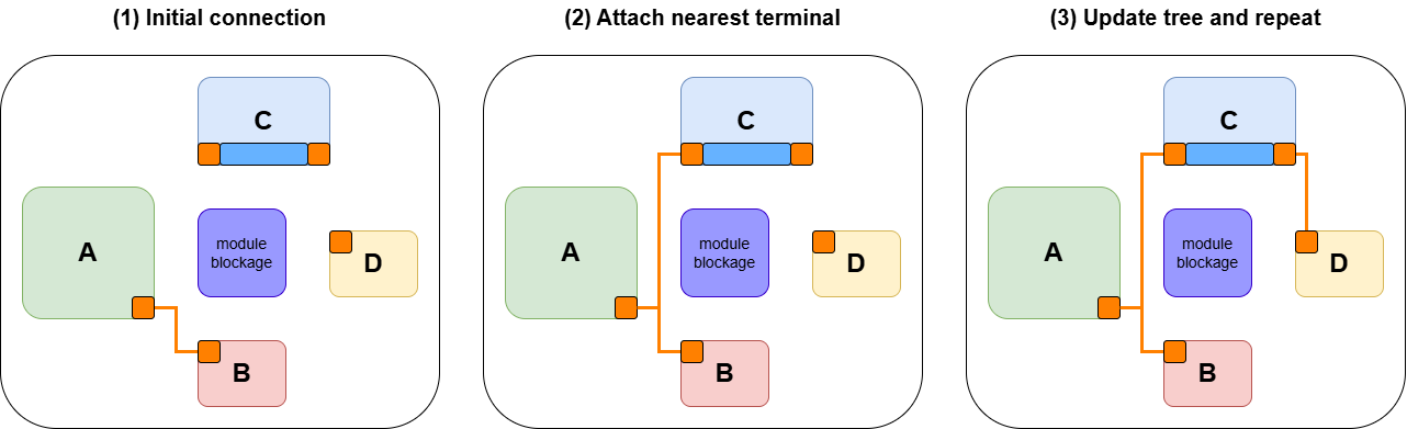
The incremental-tree procedure is:
- choose a legal initial pair, or reuse an existing connected routing object;
- initialize the current routing tree from that connection, bus, plate, or other usable routing object;
- identify the nearest legal connection from an unconnected terminal to the existing tree;
- attach the terminal;
- update the tree;
- repeat until the required endpoints are connected.
The next connection therefore searches for the nearest accessible point on the existing tree, not necessarily the first routed terminal.
This allows later branches to reuse:
- an existing same-net bus;
- an already routed backbone;
- a capacitor-plate edge;
- an earlier branch of the incremental tree.
When a safe same-layer backbone already exists, the router can reuse that geometry rather than constructing an independent parallel path.
Nearest-Connection Policy
The routing policy applies the same locality principle at several levels.
| Existing routing object | Preferred connection strategy |
|---|---|
| Long module bus | Use the nearest useful bus edge |
| Existing incremental tree | Use the nearest legal tree access |
| Compatible same-layer buses | Prefer a direct same-layer bridge |
| Capacitor plate | Use the generator-defined safe plate edge |
| Guard ring | Use the nearest legal connectable edge |
| Ordinary external terminal | Use exported access or conservative boundary access |
The same locality policy is used across supported nets and module families.
It is intended as a general top-level strategy for selecting physically nearby legal access geometry.
Module Blockages and Routing Corridors
Generated modules are treated conservatively as occupied regions during inter-module routing.
The router should therefore avoid passing laterally through unrelated module interiors, especially regions containing active devices or local routing.
The routing plan records module blockage regions and useful whitespace corridors.
Candidate routes that interact with unrelated module blockages are penalized, while available inter-module or outside whitespace corridors are preferred.
This preserves the hierarchy: top-level routing connects module interfaces, and avoid using the child-cell interior as free routing space.
Routing Sequence
The implemented routing flow separates the main responsibilities into several routing steps and policies.
Keeping these stages separate allows each routing object to use a physical connection policy appropriate to its geometry.
Current Prototype Limitations
The routing implementation is a prototype for the evaluated module families and full-flow case.
Several limitations remain.
Routing-layer freedom
Generator-defined buses and access structures are currently associated with specific metal-layer policies.
This simplifies module integration but reduces the routing-layer freedom available to the top-level router.
When two unrelated nets require incompatible paths on the same fixed layer, the present flow may not always have sufficient freedom to avoid a conflict.
No general rip-up and reroute
The current flow does not implement a complete negotiated-congestion, rip-up-and-reroute system.
A locally reasonable early connection can therefore restrict a later net when routing resources are limited.
No differential-route balancing
The current prototype does not optimize differential interconnect for matched length, matched parasitics, or full routing symmetry.
Matching-sensitive local routing remains primarily a responsibility of the generated module.
Verification boundary
The routing checks described by the flow validate interface consistency and the expected routing tasks.
They do not replace final DRC, LVS, parasitic extraction, or post-layout simulation.
The reported routing result should therefore be interpreted as hierarchical flow integration rather than sign-off routing.