Manual Layout Study
The automatic layout work was preceded by a manual study of selected analog layout techniques using a two-stage operational amplifier.
The purpose of the study was not to identify one universally optimal layout style. Instead, it was used to determine which physical effects different layout techniques target, how those effects should be evaluated, and which information should later be preserved by an automatic flow.
Reference Layout Situations
The reference amplifier contains several recurring analog layout situations:
- a matching-critical differential pair;
- current-mirror structures;
- output-connected devices;
- a Miller compensation capacitor;
- source and bulk connection issues;
- substrate/well isolation structures.
These situations later become either generated module families or explicit physical-design metadata.
Controlled Layout Variants
Four manual variants were used to separate the main layout decisions.
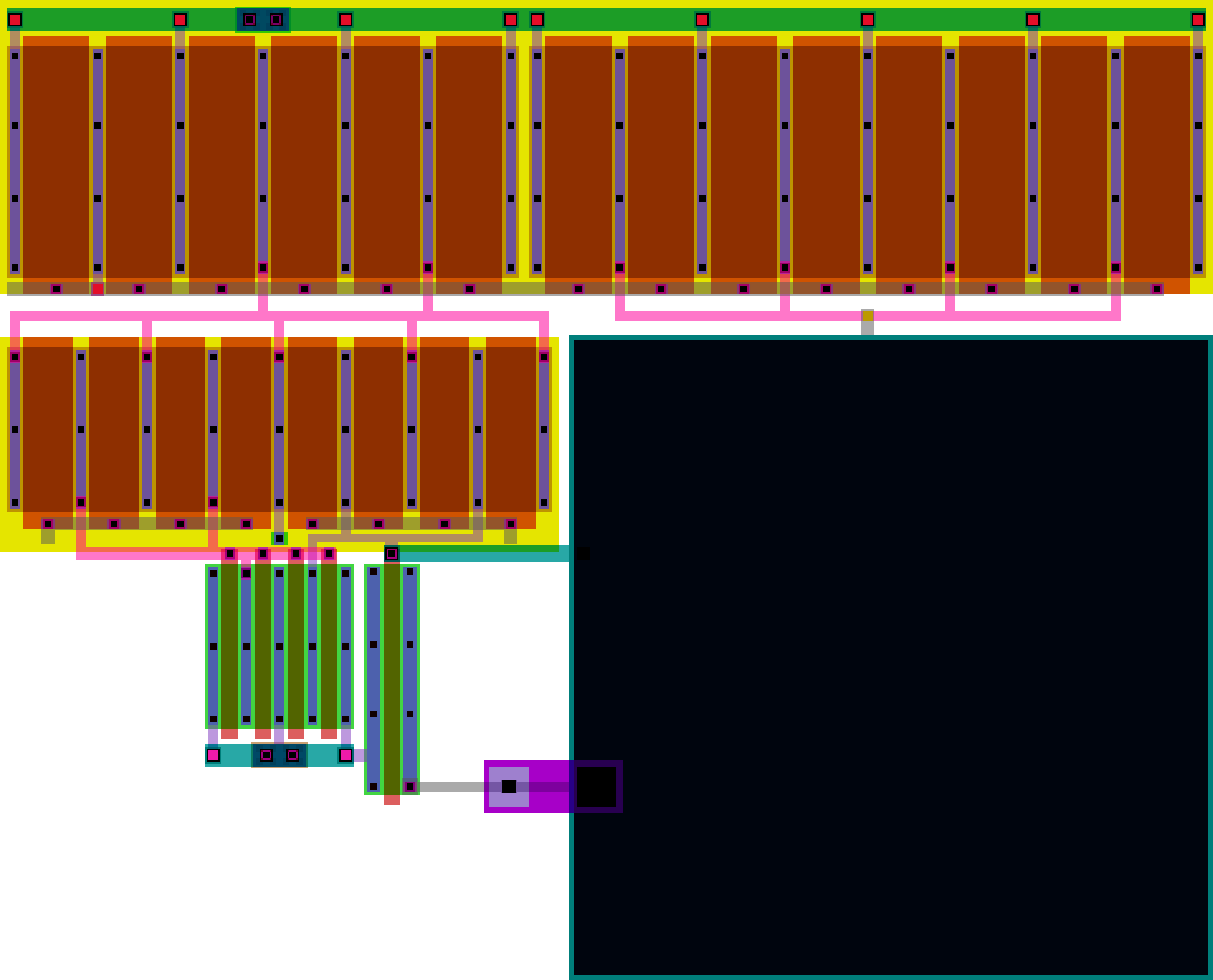
Variant A. Clustered baseline without guard rings. Layout boundary: 36.7 µm × 29.6 µm.
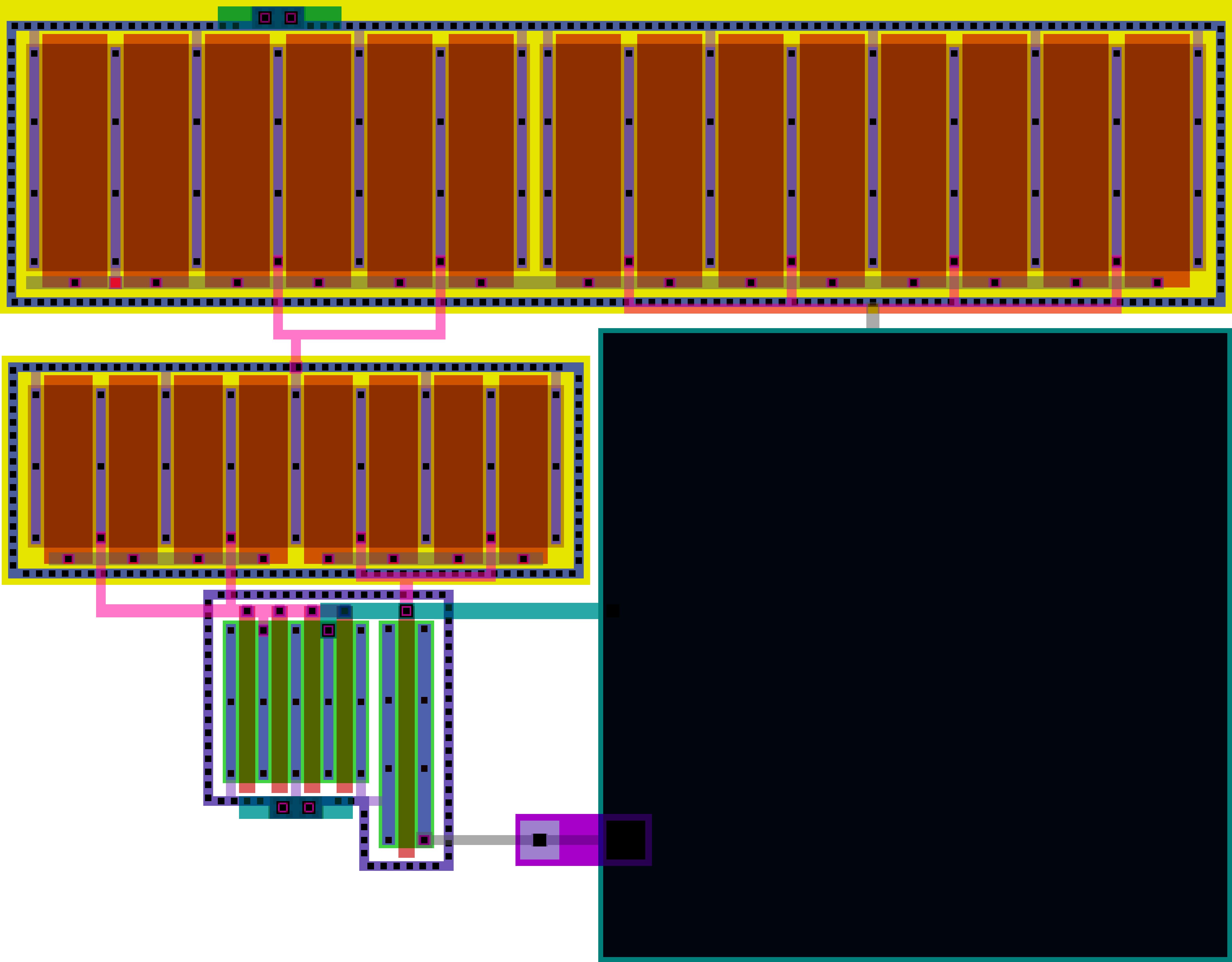
Variant B. Baseline with module-level guard-ring structures. Layout boundary: 37.9 µm × 29.6 µm.
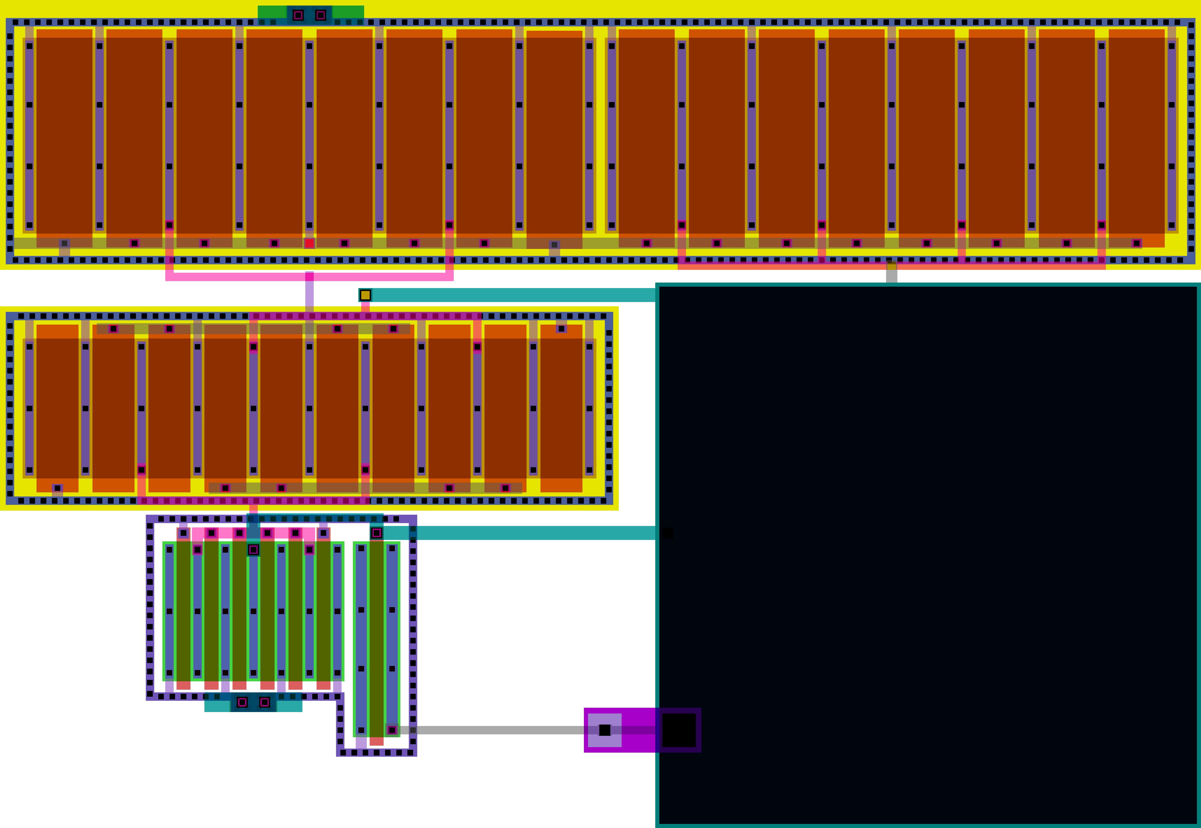
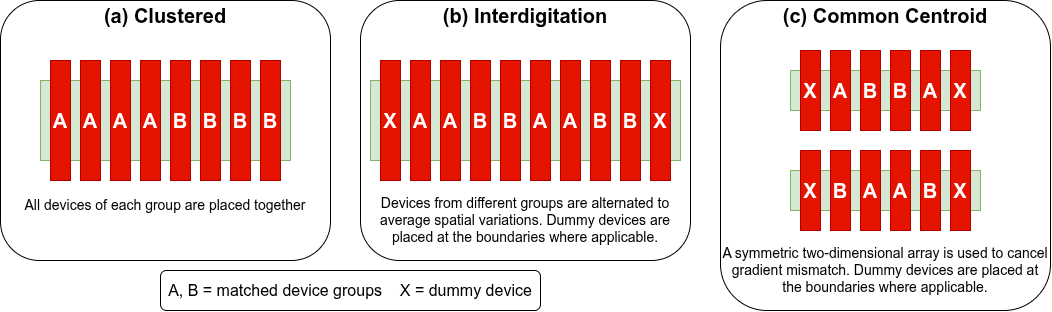
Variant C. Matching-oriented variant using interdigitation. Layout boundary: 42.9 µm × 29.6 µm.
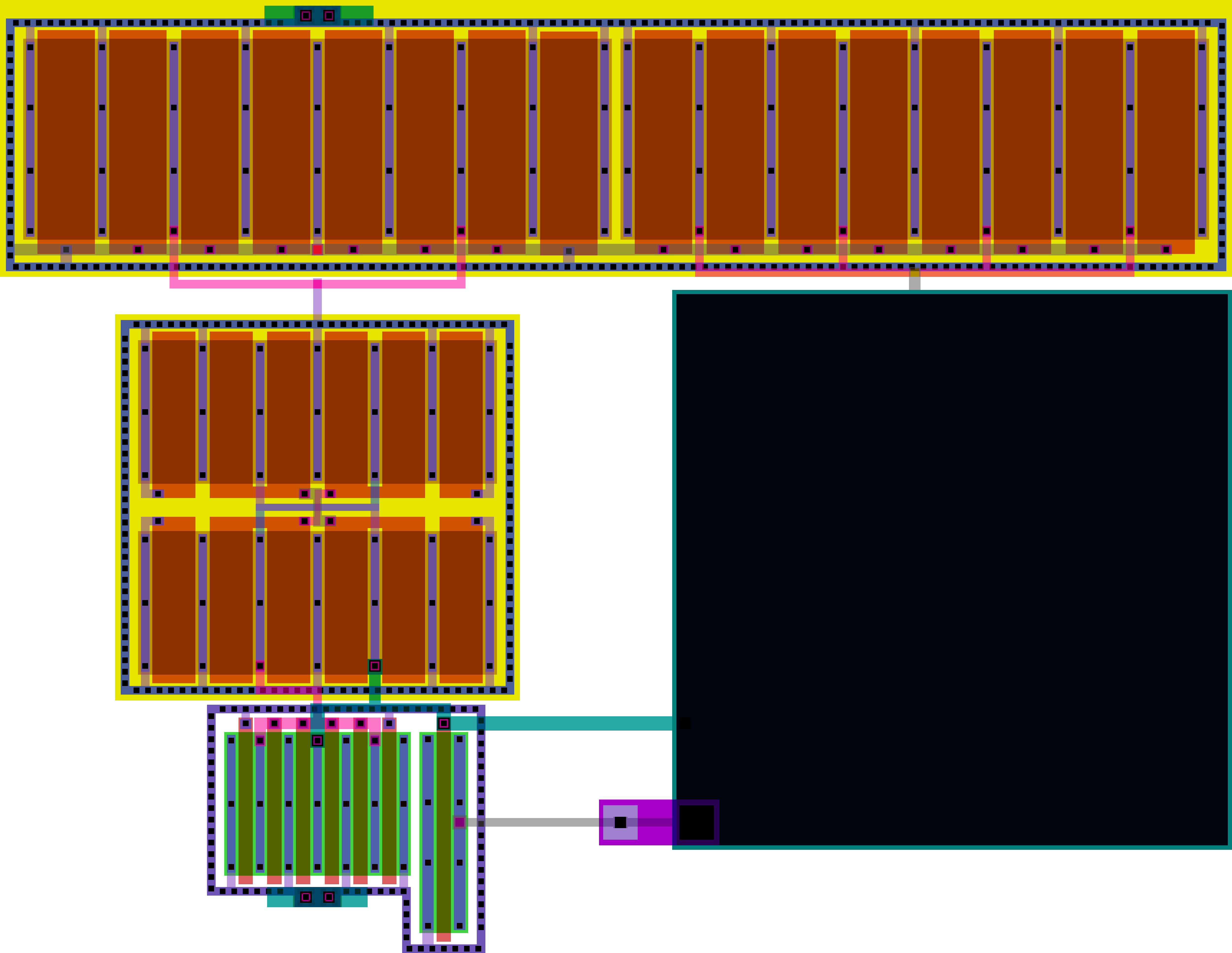
Variant D. Matching-oriented variant with a common-centroid differential pair. Layout boundary: 42.9 µm × 33.2 µm.
The comparisons are organized as controlled changes:
- A → B: guard-ring insertion;
- B → C / D: matching-oriented placement.
The schematic topology remains unchanged while the selected physical layout decision is varied.
Spacing Sensitivity
A spacing sweep was used to test whether increasing the physical separation between selected layout groups strongly changes the amplifier response in the evaluated setup.
| Metric | Pre-layout | 1.0 s₀ | 3.0 s₀ | Observation |
|---|---|---|---|---|
| GBW | 9.751 MHz | 9.574 MHz | 9.574 MHz | Post-layout shift, then essentially flat |
| Phase margin | 70.609° | 70.092° | 70.095° | Post-layout shift, then negligible sweep change |
| Positive slew rate | 27.042 V/µs | 26.133 V/µs | 26.120 V/µs | Small monotonic sweep change |
| Selected critical parasitics | — | baseline | < 0.5% change | Spacing is not dominant here |
Guard-Ring Isolation
Guard-ring insertion targets substrate and well-domain coupling. The two manual layouts are therefore compared using a controlled body-domain disturbance model.
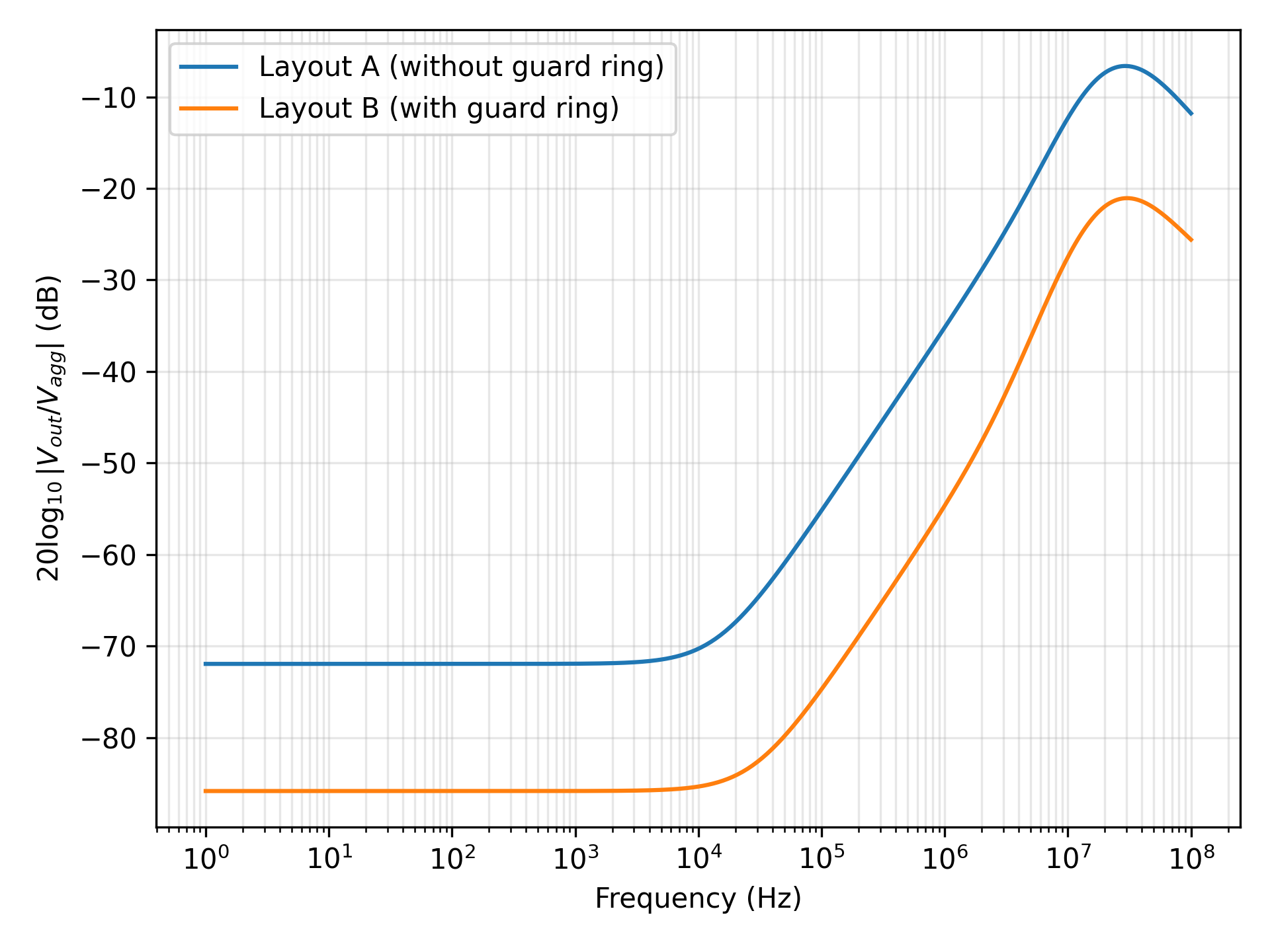
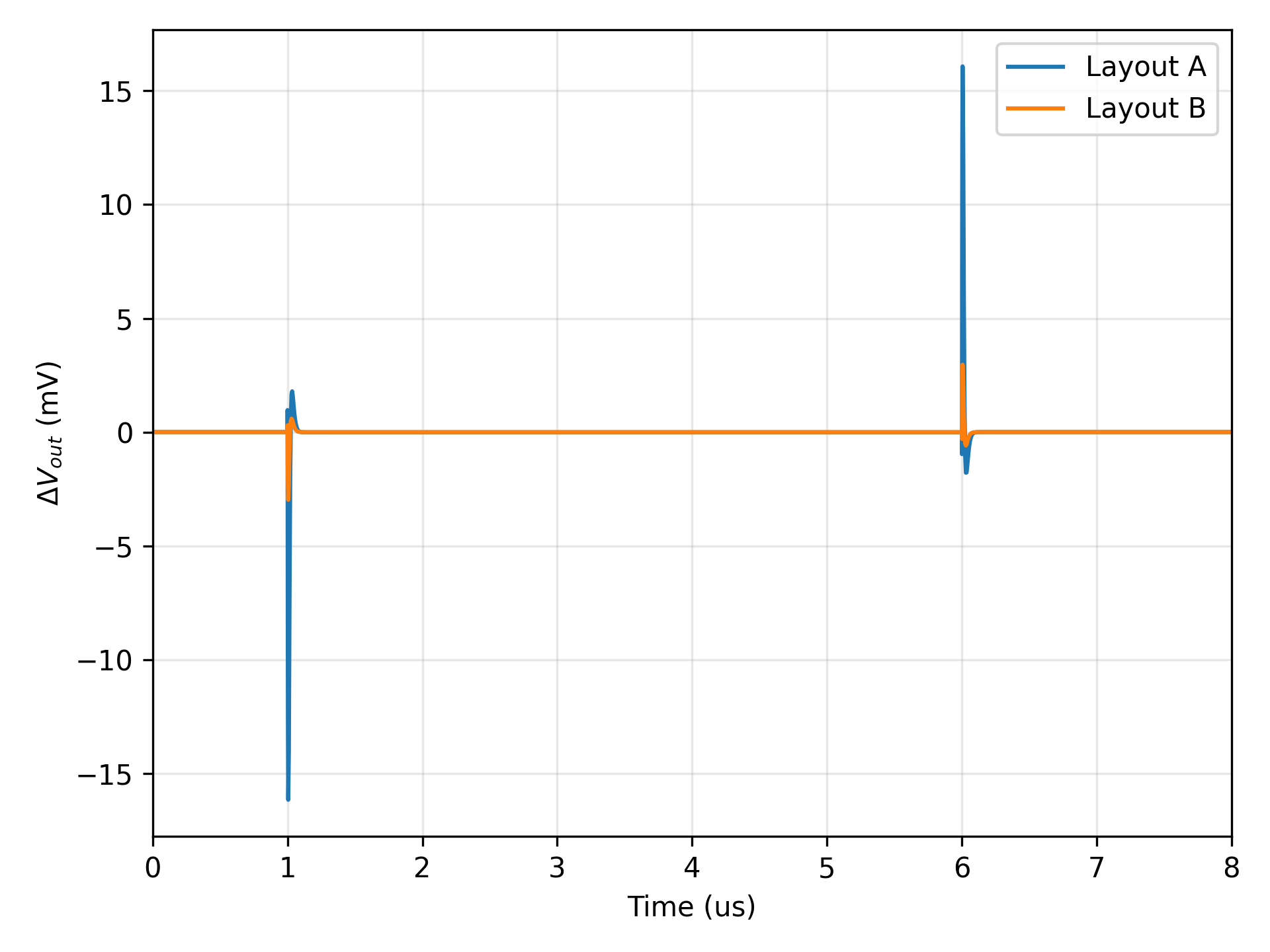
The model uses normalized disturbance-transfer factors to distinguish the guarded and unguarded body domains.
Matching-Oriented Evaluation
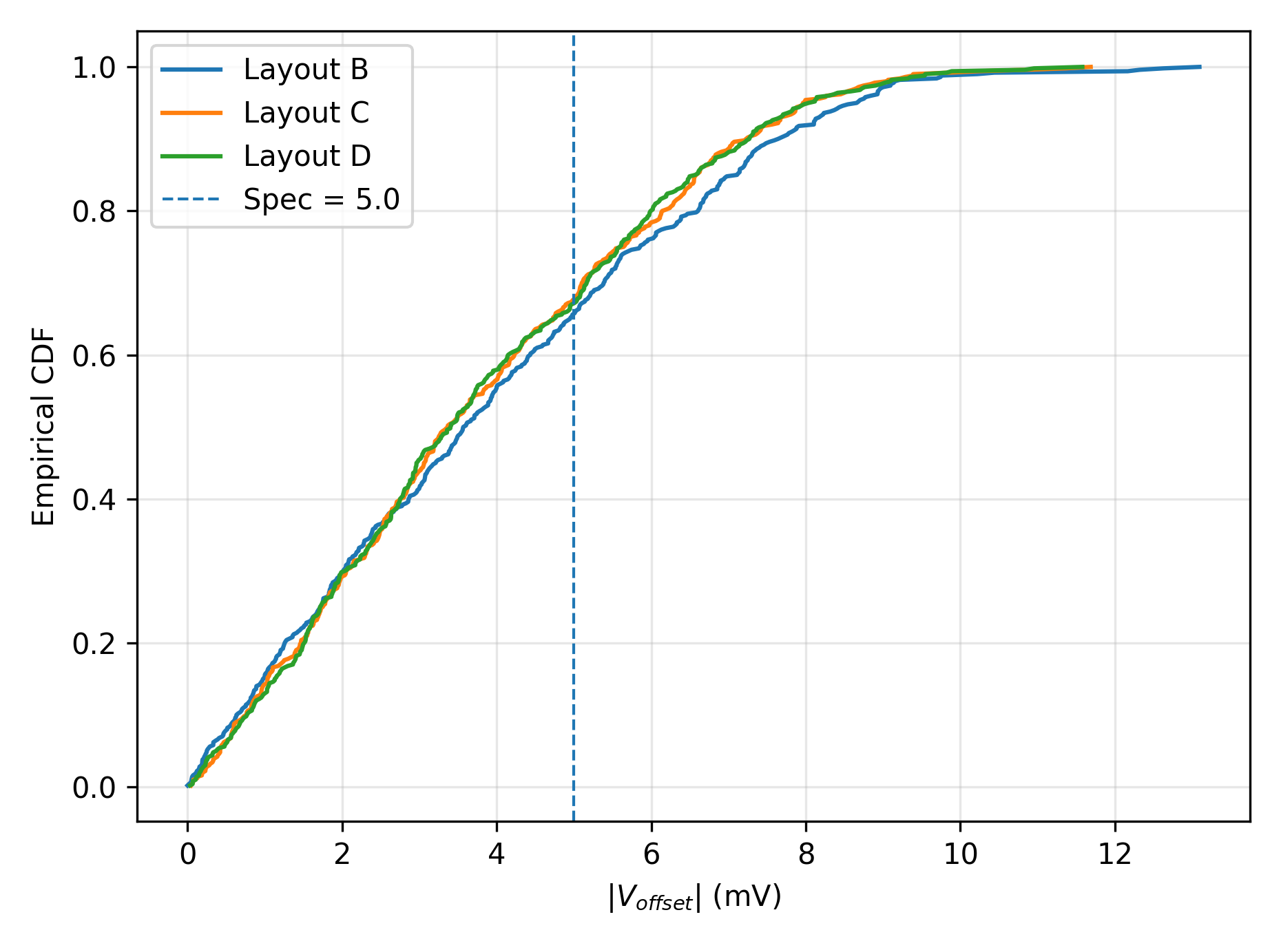
Matching-oriented layout techniques are evaluated statistically because their intended benefit appears primarily in mismatch sensitivity, distribution spread, and tail behaviour rather than as a large shift of the nominal operating point.
| Metric | Clustered B | Interdigitated C | Common centroid D |
|---|---|---|---|
| std(|Voffset|) | 2.67 mV | 2.45 mV | 2.44 mV |
| p90(|Voffset|) | 7.64 mV | 7.23 mV | 7.27 mV |
| p10(CMRR) | 62.57 dB | 63.02 dB | 63.03 dB |
| p10(PSRR) | 61.77 dB | 62.16 dB | 62.17 dB |
The mean values remain close. The clearer difference appears in spread and distribution tails. Variants C and D also remain close under the adopted simplified model.
The Monte Carlo model is comparative rather than process-calibrated. Behavioural threshold-voltage perturbations represent residual random, gradient, and edge-environment related mismatch terms.
From Manual Study to Automation
The manual study provides the basis for later automation decisions.
| Manual observation | Automation implication |
|---|---|
| Current mirrors require compact ratio matching | Shared-diffusion interdigitation |
| Differential pairs benefit from two-dimensional symmetry | Common-centroid array generation |
| Dummy devices define the local edge environment | Generator-level dummy policy |
| Guard rings are extended physical domains | Explicit guard-ring geometry and separate routing |
| PMOS well relations constrain legal placement | Well-domain metadata and post-placement repair |
| Buses and capacitor plates provide extended routing access | Explicit access geometry and access-aware routing |
The important transition is therefore not from one manual layout directly to one generated layout. The manual study first identifies the physical purpose of each technique; the resulting knowledge is then abstracted into reusable policies for generation, placement, and routing.