Full-Flow Case Study
The complete prototype flow is demonstrated on a representative two-stage operational amplifier.
The purpose of the case study is not to claim general analog-layout synthesis. It tests whether generated modules and their exported interfaces can be carried consistently through placement, well-domain handling, hierarchical assembly, and top-level routing.
Generated Module Set
The case contains six generated module instances:
| Count | Module |
|---|---|
| 1 | NMOS cascode current mirror |
| 1 | PMOS differential pair |
| 1 | PMOS simple current mirror |
| 2 | Single-transistor modules |
| 1 | MIM compensation capacitor |
All modules remain hierarchical child cells during top-level assembly.
Automatic Integration Flow
The case passes through the following stages:
- module generation;
- placement-input construction;
- analog-aware multistart B*-tree placement;
- post-placement n-well spacing repair;
- hierarchical child-cell assembly;
- local same-domain n-well bridge insertion;
- guard-ring routing;
- point-to-point signal routing;
- multi-terminal signal routing;
- flow-level interface validation.
Full-Flow Layout
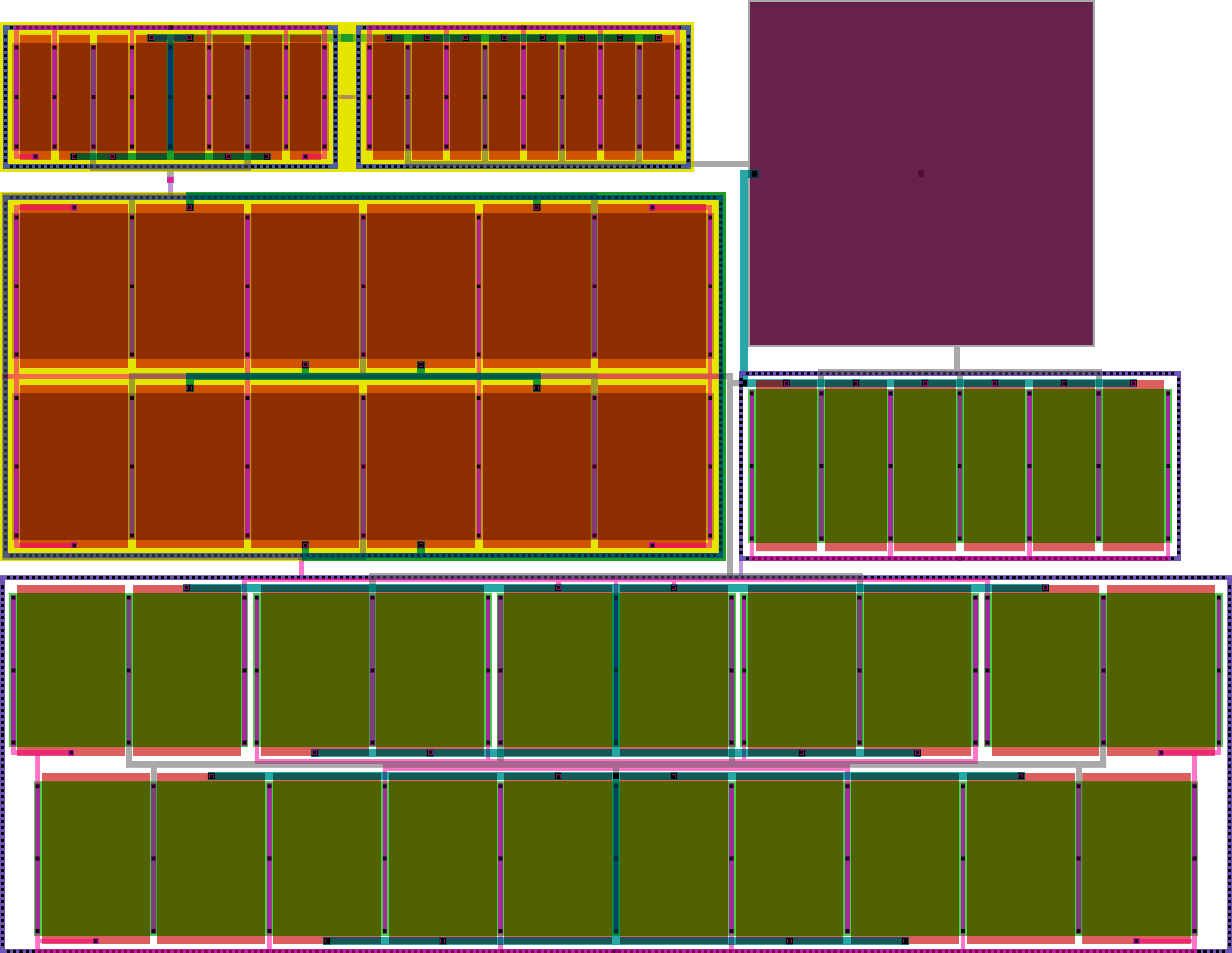
Integration Records
| Item | Result |
|---|---|
| Generated module instances | 6 |
| Selected placement seed | analog-row-compact |
| Effective placement boundary | 80.70 µm × 62.00 µm |
| Aspect ratio | approximately 1.30 |
| Different-n-well spacing penalty | reduced to zero |
| Same-domain n-well bridge | 1 |
| Guard-ring routing tasks | 3 |
| Point-to-point routed signal nets | 2 |
| Multi-terminal routed signal nets | 2 |
What the Case Demonstrates
Hierarchical preservation
Matched-device patterns, dummy devices, local buses, and topology-specific local routing remain inside their generated modules. The top-level flow works with exported module interfaces rather than reinterpreting internal geometry.
Domain-aware integration
Placement is followed by a dedicated well-domain repair stage. Different n-well spacing is legalized while same-domain PMOS modules can remain close enough for a compact local n-well bridge.
Different routing objects require different policies
Guard rings are treated as extended domain geometries rather than ordinary point pins. Point-to-point nets use access-safe endpoints, while multi-terminal nets can reuse existing buses, capacitor plates, or an existing incremental routing tree.
Prototype Scope
The evaluated result supports the architecture of the proposed manual-to-automatic flow for the selected case.
It does not establish:
- arbitrary analog-topology coverage;
- technology-independent generation;
- parasitic-optimal placement or routing;
- differential-route balancing;
- dynamic routing-layer selection and conflict resolution;
- final DRC/LVS, parasitic extraction, and post-layout verification.