Automation-Oriented Representation
A circuit netlist defines devices and electrical connectivity, but it does not fully describe the physical intent required for analog layout.
Matching relations, dummy structures, guard rings, well domains, source and bulk relations, terminal geometry, and legal routing access all affect physical implementation. If this information is discarded after module generation, later placement and routing stages must reconstruct analog intent from incomplete geometric or connectivity information.
The representation used in this work therefore preserves both geometry and selected analog-aware metadata across the automatic flow.
Why a Netlist Is Not Enough
Consider several common analog layout situations:
- a differential pair requires pair-aware matching and symmetry;
- a current mirror requires matched organization and local connectivity;
- a PMOS module belongs to an n-well domain that constrains placement;
- a guard ring is an extended connectable region rather than a point pin;
- a capacitor plate may provide an extended top-level routing interface;
- a terminal may contain geometries that are electrically equivalent but not equally suitable as top-level routing access.
These properties are relevant to physical design, but they are not fully represented by ordinary net connectivity.
The automatic flow therefore uses an intermediate representation that keeps selected layout intent available to downstream stages.
Representation Flow
The information path from circuit-level intent to physical integration is summarized below.
Each stage repackages the circuit and layout information for the next physical-design task. The generated module interface is the central boundary: internal analog layout remains inside the child cell, while placement and routing operate on the exported geometry and metadata.
Generated Module Interface
Each generated module exposes a compact interface describing the information required outside the child cell.
| Exported information | Purpose in the automatic flow |
|---|---|
| Module boundary | Describes the hierarchical geometric extent of the generated cell |
| Placement footprint | Provides the geometry used for packing, spacing, and overlap checks |
| External terminal geometry | Identifies the physical geometry belonging to externally visible terminals |
| Routing access geometry | Identifies locations or regions suitable for top-level connection |
| Guard-ring geometry | Provides extended regions for bulk and guard-ring connectivity |
| Well-domain information | Supports same-nwell domain grouping, local n-well bridge decisions, and different-nwell spacing repair |
| Source/bulk relation | Preserves body-domain connectivity requirements |
| Family and topology metadata | Retains structural context for downstream policies |
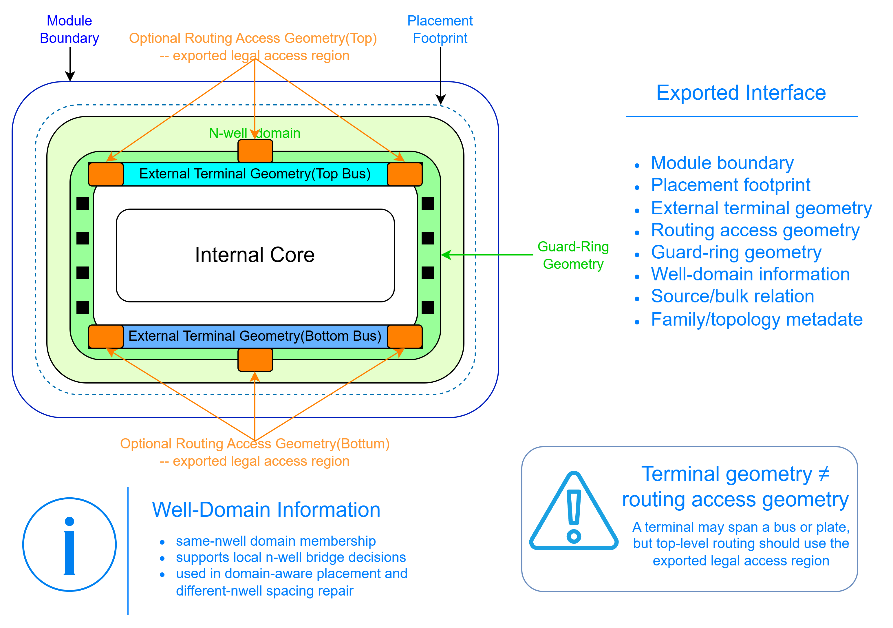
The interface is intentionally smaller than the complete internal layout. Downstream stages do not need to reconstruct every finger, dummy device, or local wire in order to place and connect the module.
Module Boundary and Placement Footprint
The geometric boundary of a hierarchical cell and the geometry used by a placer do not always serve the same purpose.
The module boundary describes the generated child-cell geometry.
The placement footprint describes the region that should participate in top-level packing and spacing decisions. Depending on the module, this may be represented by one rectangle or by multiple rectangles when a single bounding box would introduce excessive empty space, for example for a T-shaped module such as a Wilson current mirror.
Keeping these concepts separate allows the placement representation to remain conservative without forcing every generated structure to behave as a simple rectangular device.
Terminal Geometry and Routing Access
Electrical terminal geometry and top-level routing access are treated as related but distinct concepts.
A generated terminal may contain an extended bus, plate, or several electrically equivalent conductive shapes. These geometries define the physical extent of the terminal. The downstream router, however, should not assume that every point on this geometry is equally suitable for a new top-level connection.
The exported routing-access information identifies preferred or legal connection regions according to the local module construction. Depending on the terminal, this may correspond to a bus edge, a boundary extension, an existing access segment, or an extended plate edge.
The representation therefore distinguishes:
terminal geometry — the conductive geometry electrically associated with an external terminal;
from
routing access geometry — the subset or extension intentionally exposed for safe and useful top-level connection.
This distinction allows the top-level router to reuse generator-defined access structures while avoiding unnecessary intrusion into the module interior.
Internal Closure and Top-Level Responsibility
The hierarchical flow separates local analog structure from placement-dependent integration.
| Responsibility retained inside the generated module | Responsibility handled at top level |
|---|---|
| Finger ordering | Relative module placement |
| Matching-oriented local organization | Inter-module routing |
| Dummy-device insertion | Guard-ring and bulk-domain connection between modules |
| Local gate and drain/source buses | Placement-dependent n-well bridges |
| Diode connections | Point-to-point signal routing |
| Internal stack-node routing | Multi-terminal routing |
| Topology-specific local wiring | Assembly of hierarchical child cells |
This separation reduces the amount of analog structure that the top-level flow must rediscover.
For example, a common-centroid differential pair remains a complete child module. The placer sees its footprint and domain information, while the router works with its exported external access. Neither stage needs to reconstruct the internal common-centroid pattern.
Analog-Aware Metadata
Geometry alone is not sufficient for all downstream decisions.
The representation also retains selected semantic information such as:
- module family;
- topology role;
- device polarity;
- matching relation;
- well-domain membership;
- source and bulk relation;
- guard-ring information;
- terminal and access classification.
The metadata carries the information required by downstream structure-aware physical-design stages.
Central principle: analog-aware metadata carries selected manual layout intent into automatic physical implementation.
Why the Representation Matters
The representation provides the interface between the conceptual layout framework and the later implementation stages.
It allows different stages to work at different levels of abstraction:
- generators handle local analog structure;
- placement operates on footprints, relationships, and domain information;
- well-domain repair works with placement-dependent domain geometry;
- hierarchical assembly preserves generated child cells;
- routing operates on external terminals and explicit access geometry.
This avoids two undesirable extremes.
The first is a purely geometric flow in which analog intent is lost after generation.
The second is a monolithic flow in which every downstream stage must understand the complete internal layout of every analog topology.
The adopted representation instead exposes only the physical and semantic information required at module boundaries.